Most hardware startups realize the importance of DFM for injection molding only at advanced stages of tooling. At that stage, even minor modifications require expensive tool rework, causing delays and significant cost overruns.
DFM is not a checklist to run through at the end of your design process. It is a discipline that must shape every decision from the earliest concept stages. Applied correctly, it reduces manufacturing costs, improves yield, shortens cycle times, and makes your product far easier to scale when the time comes. This is why many global teams now rely on mechanical product engineering for startups in the US and Europe to ensure DFM is embedded right from the concept stage.
This article covers 7 proven techniques for injection molding cost reduction, that directly impact manufacturing costs for IoT enclosures with real case studies that show exactly what poor decisions look like in practice, and what thoughtful design can save.
1. DFM for Injection Molding: Costly Gate Design Mistakes
How to optimize gate location in injection molding to avoid costly defects

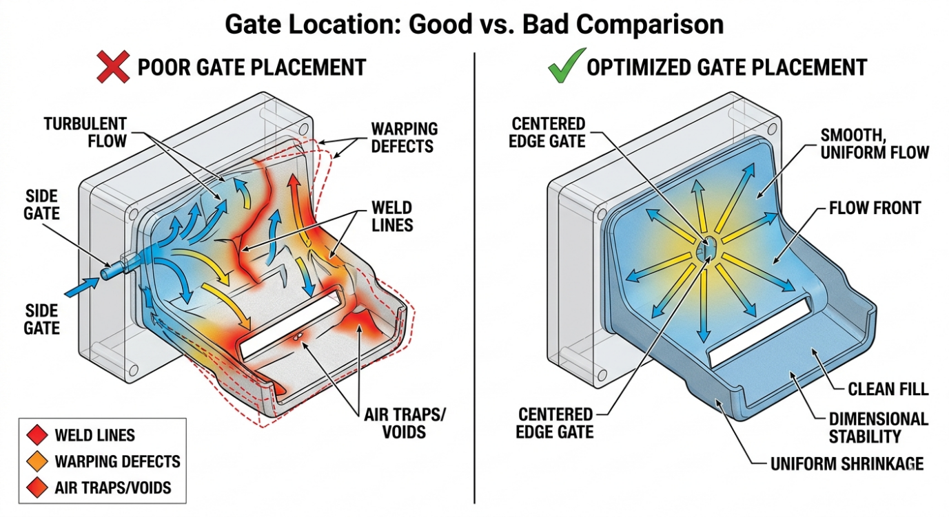
In injection moulding, the gate is the entry point through which molten plastic flows into the mould cavity. A well-planned injection molding gate design determines almost everything about how your part fills, where weld lines form, and whether the finished part warps or remains dimensionally stable.
There are several gate types to consider: edge gates are simple and low-cost but can leave visible marks; pin gates offer cleaner aesthetics but require more complex tooling; hot runner systems eliminate gate vestiges entirely but carry significantly higher upfront tooling costs. The right choice depends on your part geometry, production volume, and cosmetic requirements, especially when targeting injection molding cost reduction without compromising quality.
Flow balance is the critical concept. When plastic enters from an optimally positioned gate, it fills the cavity evenly, pushing air out through vents uniformly, and cooling with consistent shrinkage across the part. Poor gate placement creates race tracking where plastic flows faster through thicker sections and meets itself at weld lines. These weld lines are structural weak points and often cosmetically visible.
Using mold flow analysis, engineers can simulate and validate gate positions before committing to tooling. This is not an expensive luxury; it is one of the most cost-effective investments in the entire product development process.
Case Study: Consumer Electronics Startup, United States
Problem: Incorrect gate placement caused uneven material flow, leading to high rejection rates and visible warping in the finished enclosures.
Impact: Significant scrap costs are accumulating with every production run. Assembly delays and quality control failures.
Fix: Flow simulation used to identify optimal gate repositioning. Tooling was modified before high-volume production commenced.
Result: Defect rate was eliminated. Approximately $20,000 saved in scrap and rework costs.
Key Insight: Flow balance directly determines your cost per accepted part.
02.Parting Line Design Mistakes That Drive Up Tooling Cost
How parting line design affects tooling cost in plastic parts
The parting line is where the two halves of your injection mould meet. Effective parting line design in injection molding is one of the most consequential design decisions in plastic part development and one that is frequently underestimated by startups unfamiliar with tooling economics.
In DFM for injection molding, parting line strategy plays a critical role in controlling tooling complexity and overall cost.Every time your part geometry forces the mould to split in a complex direction, or requires side actions and lifters to release undercuts, your mold design complexity cost increases These mechanisms drive up cost, add machining time, increase mould maintenance requirements, and introduce additional failure points in production. Simpler parting geometry equals cheaper, more reliable tooling and contributes directly to injection molding cost reduction.
Flash defects in of plastic that form at the parting line are another consequence of poor strategy. When mould halves do not align perfectly, or when injection pressure forces plastic into tiny gaps, flash forms and must be removed manually or through secondary operations. At volume, this adds meaningful labor cost.
The best approach is to define your parting line during the earliest stages of enclosure design, not as a downstream manufacturing consideration. Place parting lines on non-cosmetic edges where possible. Design draft angles that allow clean release. Eliminate undercuts through geometry changes rather than mechanical mould features wherever feasible.
Case Study: Industrial IoT Startup, Germany
Problem: Complex parting geometry required multiple side-actions and non-standard mould split directions to accommodate the enclosure design
Impact: Tooling cost increased by €35,000 over initial estimates. Extended lead time for mould manufacture.
Fix: Design team simplified the split line geometry, eliminating two side actions through minor enclosure shape changes
Result: Tool cost reduced by 20%. Manufacturing setup time shortened. Ongoing maintenance costs have been lowered.
Key Insight: Simpler geometry is always cheaper to tool and easier to maintain
3. DFM for Injection Molding: Snap-Fit vs Screws to Reduce Assembly Cost
How to reduce assembly cost in hardware products using snap-fits

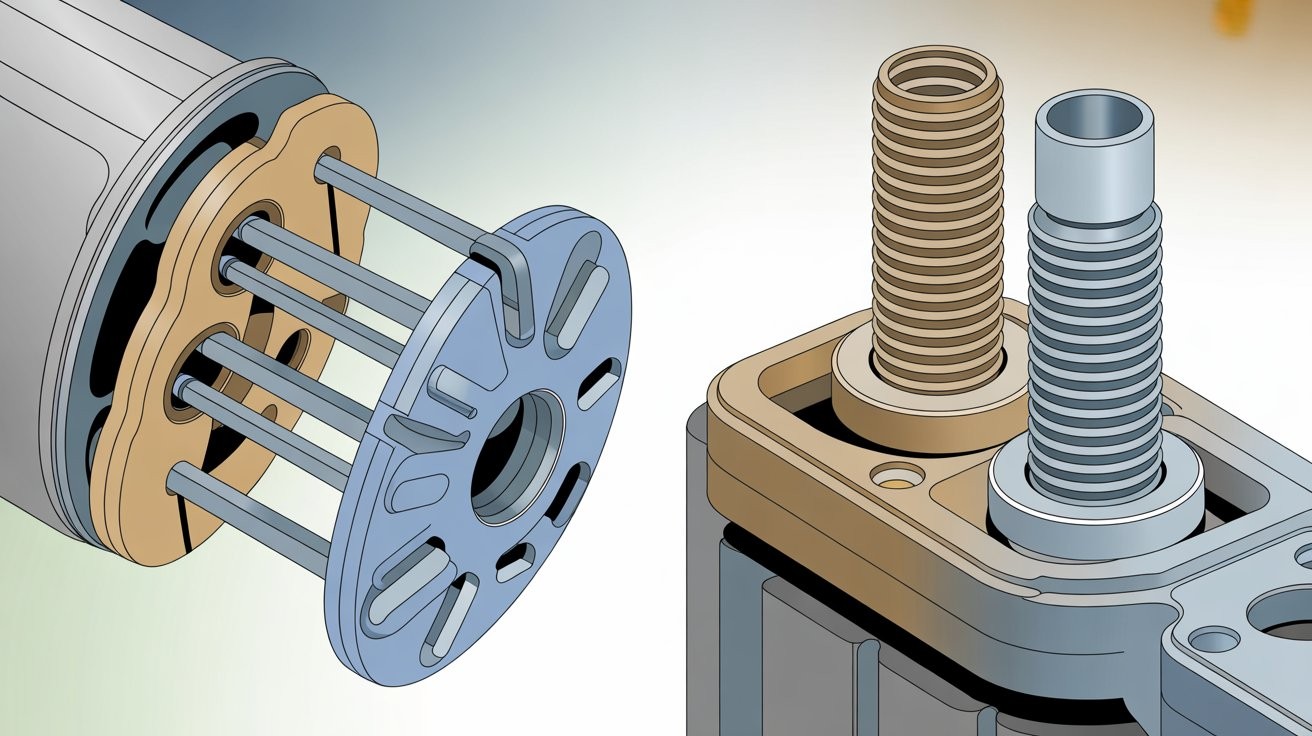
Every fastener in your assembly has a cost. Not just the cost of the screw itself, though that adds up at volume, but the cost of the driver tool, the assembly time per unit, the torque specification and quality check, the potential for cross-threading or over-torquing, and the service time when a field technician needs to open the device. This is why the decision between snap fit design vs screws has a direct impact on overall manufacturing efficiency and cost.
Snap-fit joints, when designed correctly, eliminate most of these costs. A well-designed cantilever snap-fit can be engaged in a fraction of a second with no tools, no fasteners, and no torque variability. At a production volume of one million units, reducing assembly time by thirty seconds per unit translates directly into thousands of dollars in labor savings making it a key strategy in IoT enclosure design for manufacturing.
The trade-off is engineering complexity and material discipline. Snap-fits require careful geometry to achieve the right deflection force without fracturing the feature. They require consistent material properties, particularly elongation at break and appropriate draft angles for mould release. They also need to accommodate repeated assembly cycles if the product will be serviced in the field.
A hybrid approach works well for many IoT enclosures: snap-fits for the primary closure, with one or two screws at stress-bearing points or where tamper evidence is required. The key is deliberate design rather than defaulting to screws because they are familiar.
Case Study: Smart Device Startup, United Kingdom
Problem: Screw-based enclosure design required dedicated assembly tooling, multiple manual steps per unit, and ongoing quality checks on torque consistency.
Impact: High assembly labor cost per unit. Production line bottleneck at the fastening station.
Fix: Enclosure redesigned with cantilever snap-fit closure, reducing manual assembly steps from six to two per unit.
Result: 35% reduction in assembly cost per unit. Production throughput increased. Labor deployment shifted to higher-value tasks.
Key Insight: Assembly design is a hidden cost driver that compounds at every unit produced.
04.Boss Design Mistakes That Cause Failures and Rework
How to design screw bosses in plastic parts without failure
Bosses, the cylindrical protrusions that accept screws or press-fit inserts, are among the most failure-prone features in plastic enclosure design. They are also among the most frequently under-engineered, because they appear simple and are easy to add as an afterthought. In boss design in injection molding, this tendency often leads to avoidable performance and manufacturing issues.
In DFM for injection molding, a core aspect is the boss design, its a critical factor that directly impacts both product reliability and manufacturing cost. The failure modes are predictable. Bosses that are too thick relative to the surrounding wall thickness create sink marks in plastic on the cosmetic surface, a visible depression caused by differential cooling and shrinkage. Bosses that are too thin crack under assembly torque or during drop testing. Bosses that lack gusset reinforcement deflect under load and lose their grip on fasteners over time.
The design rules are well established: boss outer diameter should be two to two-and-a-half times the screw diameter; boss wall thickness should be fifty to sixty percent of the nominal wall thickness to prevent sinking; gussets should connect the boss to adjacent walls at forty-five degrees to distribute stress. These are not arbitrary guidelines; they reflect decades of empirical data from production environments.
Getting the boss’s design right does not add cost. It reduces it by eliminating scrap from sink defects, by preventing field failures that trigger warranty claims and replacements, and by avoiding the tooling modifications required when bosses crack during assembly testing.
Case Study: Medical IoT Device Startup, France
Problem: Boss features designed without adequate wall thickness ratios or rib reinforcement, identified only during assembly qualification testing
Impact: 20% product failure rate at assembly. Cracking at the boss features under standard torque values. Production halted.
Fix: Boss geometry redesigned with correct thickness ratios and gusset ribs added. Tooling modified with targeted steel insertion.
Result: Failure rate reduced to near zero. The assembly process stabilized. No further field returns are attributed to structural failure.
Key Insight: Small features cause major failures and major redesign costs
5. DFM for Injection Molding: How to Reduce Cycle Time and Cost
How wall thickness affects cycle time in injection molding

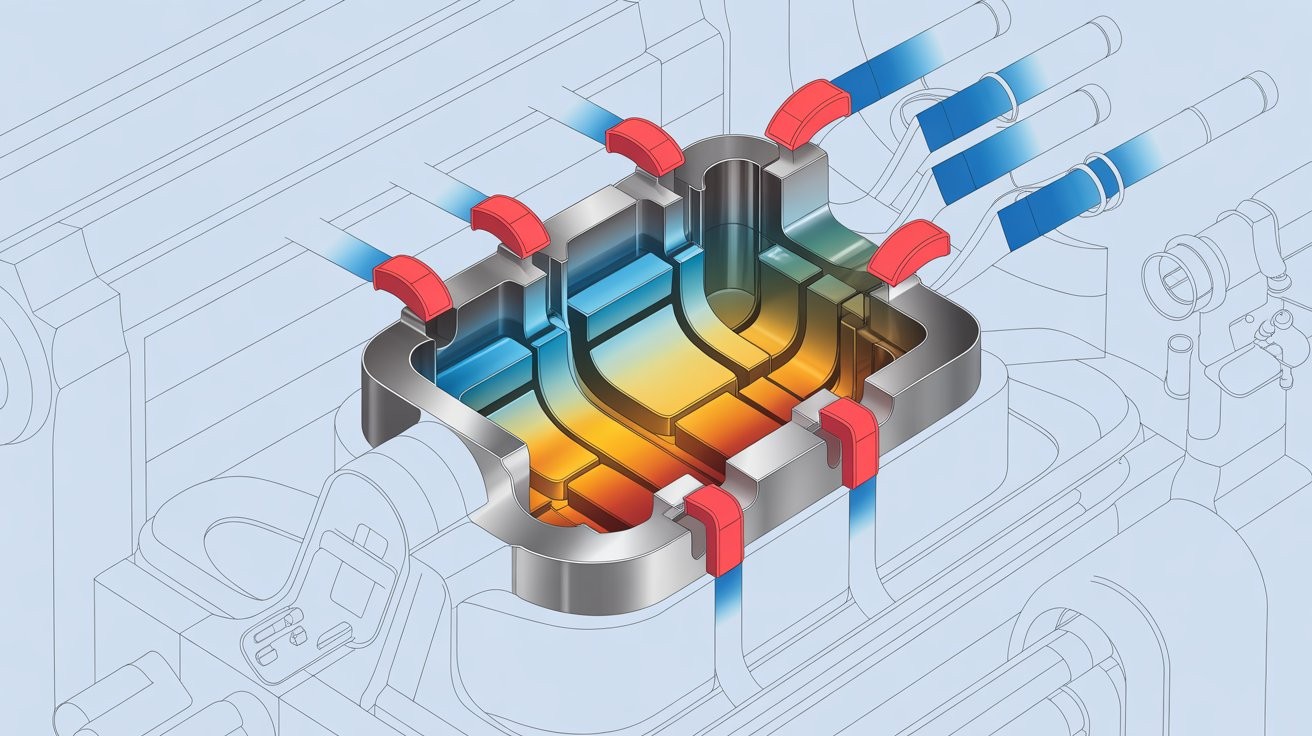
In injection molding, cycle time is money. The faster each cycle completes injection, packing, cooling, and ejection, the more parts your tool produces per shift, and the lower your cost per unit. Cooling typically accounts for sixty to seventy percent of total cycle time, making wall thickness the single most impactful design variable under your control. This is why wall thickness optimization in plastic parts is a critical focus area in cost-effective manufacturing.
Thick walls take longer to cool. The relationship is not linear; cooling time scales roughly with the square of wall thickness. A wall that is two millimetres thick cools four times faster than a four-millimetre wall. For high-volume production, small reductions in wall thickness deliver large reductions in cost per unit.
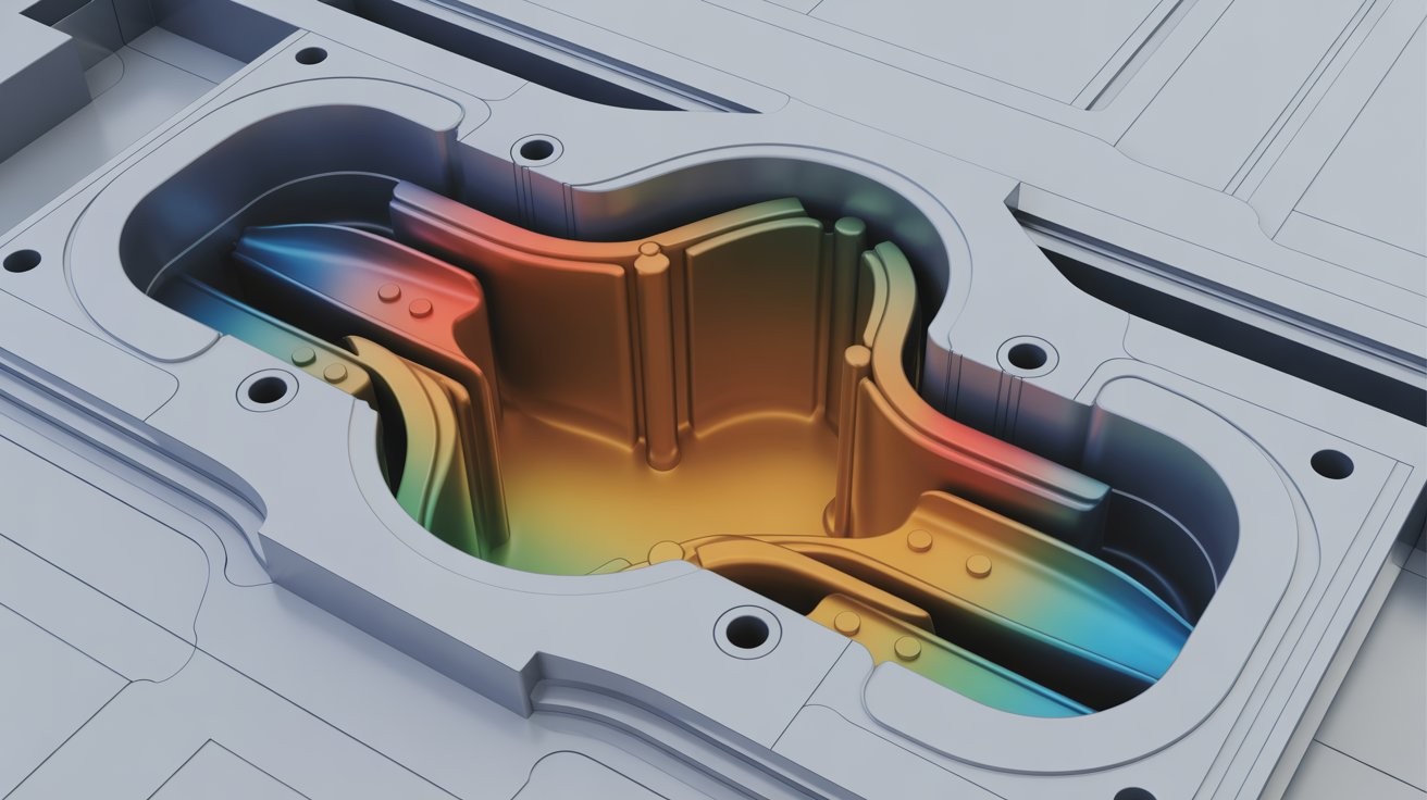
The challenge is maintaining structural integrity as walls thin. This is where ribs become essential. A ribbed wall can be fifty to seventy percent thinner than a solid wall of equivalent stiffness, dramatically reducing cooling time without sacrificing performance. Rib design follows its own set of rules, height, thickness ratio, spacing, but the engineering investment pays for itself many times over in production savings.
Uniform wall thickness is an equally important principle. Sections that vary dramatically in thickness cool at different rates, creating internal stress, warping, and sink marks. Designing for consistent thickness, with gradual transitions where changes are necessary, produces parts that cool evenly and eject cleanly.
Case Study: IoT Hardware Startup, United States
Problem: Enclosure walls are significantly thicker than structurally necessary, designed conservatively without DFM review
Impact: Cycle time increased by 15% versus the target. Cost per unit above business case threshold. Production economics not viable at the planned volume.
Fix: Wall thickness reduced and structural ribs added. Cooling channel layout reviewed and optimised in conjunction with the mould maker
Result: 20% reduction in cost per unit achieved. Cycle time brought within target. Business case restored
Key Insight: Faster cooling cycles mean lower cost at every unit of volume.
6. Multi-Cavity vs Single-Cavity: Avoid Expensive Tooling Mistakes
When to use multi cavity molds for cost-effective production
A multi-cavity mould produces multiple identical parts in each injection cycle. A four-cavity tool, for example, produces four enclosure halves per cycle, effectively multiplying throughput by four. At high volumes, multi-cavity tooling dramatically reduces cost per unit and is ultimately the right manufacturing strategy for successful products. This is a key consideration when evaluating multi cavity vs single cavity mold decisions in production planning.
In DFM for injection molding, or any robust injection molding tooling strategy must align with both design maturity and production volume. The mistake is committing to multi-cavity tooling before your design is stable and your volume projections are validated. Multi-cavity tools cost significantly more to build, often two times more than a single-cavity equivalent, and they multiply the cost of any design change. If you need to modify your enclosure after a multi-cavity tool is built, it becomes a complex and costly process. This is where a structured mechanical product engineering for startups in the US and Europe approach helps ensure tooling decisions are aligned with real-world production readiness.
The rational approach is to stage your tooling investment. Start with a single-cavity tool for initial production runs and market validation. Use this phase to identify any remaining design issues and confirm your volume ramp. Once the design is locked and demand is proven, invest in multi-cavity tooling for scale. The initial per-unit cost will be higher, but the total capital at risk is far lower.
Tooling decisions should reflect your actual business stage, not your aspirations. Many startups have invested in multi-cavity tooling for products that were subsequently pivoted or discontinued, writing off investments that a staged approach would have protected. This is particularly relevant in IoT enclosure design for manufacturing, where flexibility early on can prevent significant financial loss later.
Case Study: Consumer Electronics Startup, Netherlands
Problem: Multi-cavity tooling was ordered based on projected volumes before design was fully validated or market traction confirmed.
Impact: €50,000 upfront tooling investment at risk. Design changes required mid-production, affecting all cavities simultaneously.
Fix: Switched to a single-cavity approach for initial production. Multi-cavity investment deferred to the confirmed scale phase.
Result: 40% cost saving on initial tooling. Design iteration preserved. Scaled to multi-cavity tooling once volume was validated.
Key Insight: Match your tooling investment to your actual volume, not your ambition
7. Surface Finish Decisions That Quietly Increase Manufacturing Cost
How surface finish affects product cost in injection molding
Surface finish is where aesthetics and manufacturing economics collide. The way your enclosure looks and feels has real commercial value. It communicates quality, supports brand positioning, and influences purchase decisions. It also has a direct and often underestimated impact on tooling cost and production complexity, particularly when decisions around injection molding surface finish are made without cost awareness.
Mould polishing for a high-gloss finish requires significant additional machining time and specialist craftsmanship. Textured surfaces achieved through chemical etching or EDM (electrical discharge machining) of the mould cavity add cost proportional to the area being treated. Specifying a premium finish across the entire enclosure when only certain surfaces are visible to the end user is an unnecessary expense.
The strategic approach is selective finishing. Identify which surfaces matter: the front face, the visible edges, the area around the logo or display. Apply the premium finish only there. Non-cosmetic surfaces, internal faces, mounting flanges, and hidden panels can be left in a standard tooling finish that requires no additional processing, helping control overall mold polishing cost.
This approach also has production benefits. Highly polished mould surfaces require more careful handling and maintenance. A textured surface, by contrast, hides minor scratches and wear marks, extending the effective life of your tooling before refurbishment is needed.
Case Study: Premium Electronics Brand, Italy
Problem: Full enclosure texturing specified on all surfaces, including non-visible internal and mounting areas.
Impact: Tooling cost increased by 30% over the base estimate. Extended mould manufacturing lead time.
Fix: Selective texturing strategy applied a premium texture on front and top faces only; standard finish on non-cosmetic surfaces.
Result: Premium aesthetic preserved on customer-facing surfaces. The tooling cost has reduced significantly. Lead time shortened.
Key Insight: Strategic aesthetics deliver the brand value without the budget penalty
The Cost Is in the Design, Not the Factory

Every technique in this article shares a common principle: manufacturing cost is determined long before production begins. By the time your enclosure reaches a factory floor, the decisions that will drive your cost per unit, your yield rate, your cycle time, and your tooling investment have already been made in your CAD files. This is the core idea behind design for manufacturability injection molding.
DFM for injection molding is not about limiting your design freedom. It is about making design decisions with full awareness of their manufacturing consequences. Gate placement, parting line strategy, snap-fit geometry, boss proportions, wall thickness, tooling investment staging, and surface finish specification are all design decisions that engineering teams make every day. Making them with DFM awareness costs nothing extra. Making them without it costs a great deal. This is exactly the approach followed by Engon Technologies, where design and manufacturing considerations are integrated from the earliest stages.
The startups that scale successfully in hardware are not the ones with the biggest budgets. They are the ones who spend their budgets wisely, validating before committing, designing for the factory alongside designing for the customer, and treating manufacturability as a first-class engineering requirement from the very first concept sketch.
Ready to Reduce Your Manufacturing Costs by Up to 30%?
Before you invest in tooling, get your enclosure design reviewed using DFM principles. Our engineers identify hidden cost drivers and structural risks before they become expensive
Request Your Free DFM Design Review Today →FAQ:
DFM for injection molding (Design for Manufacturability) is the practice of designing plastic parts so they are easy, cost-effective, and reliable to manufacture. It focuses on optimizing geometry, tooling, and material choices early in the CAD stage to reduce defects, tooling cost, and production delays
DFM reduces injection molding cost by improving part design before tooling begins. It lowers cycle time through optimized wall thickness, reduces defects with better flow design, and avoids expensive mold rework. The result is lower cost per unit, higher yield, and faster production scaling.
DFM should be applied at the concept and CAD design stage, before mold tooling is created. Early application prevents costly design changes later, ensures manufacturability, and reduces time-to-market. Waiting until after tooling significantly increases cost and delays.
Common injection molding mistakes include uneven wall thickness, poor gate placement, complex parting lines, weak boss design, and overuse of screws. These issues lead to defects, longer cycle times, higher tooling costs, and increased production failures.
Single-cavity molds are best for prototyping and low-volume production due to lower cost and flexibility. Multi-cavity molds are ideal for high-volume manufacturing as they increase output per cycle. The recommended approach is to start single-cavity and scale to multi-cavity after validation
To reduce cycle time, optimize wall thickness, maintain uniform geometry, and use ribs instead of thick sections. Since cooling dominates cycle time, thinner and consistent walls significantly improve production speed and reduce cost per part.
IoT enclosure design directly impacts cost, durability, and manufacturability. Poor design leads to defects, assembly issues, and high tooling costs, while optimized design ensures efficient production, better product quality, and easier scalability.


