

Tooling is one of the largest upfront investments in any injection-molded product. For most projects, the mould itself represents 30 to 60 percent of total product development cost, and those numbers can climb fast when the design is not built with manufacturability in mind. The frustrating reality is that most tooling cost overruns are not caused by poor supplier selection or unexpected material prices. They are locked in during the design phase, often weeks or months before a purchase order is issued, highlighting the importance of engineering services for product development for engineering managers across the US and Europe to improve manufacturability before tooling begins.
Industry research indicates that approximately 70–80% of a product’s total lifecycle cost is determined during the early design phase, making design decisions one of the biggest drivers of tooling cost, manufacturability, and long-term production efficiency.
This guide walks through ten design decisions that consistently drive up injection mold tooling costs, along with practical strategies engineers and product teams can use to avoid them. Each section includes a real-world case study to show how the principles apply in practice.
Before investing in production tooling, it’s equally important to evaluate whether your product is truly ready for manufacturing. Our guide on Is Your Product Really Ready for Mass Production? explains the key engineering and manufacturability checks that help reduce production risks before tooling begins.
1. Designing Features That Require Side Actions, Sliders, and Lifters
What Are Side Actions, Sliders, and Lifters?
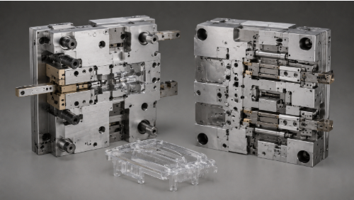
Side actions in injection molding are mechanical mechanisms built into a mold to form features that cannot be released by opening the mold along its primary axis. Sliders move horizontally to create external undercuts such as lateral holes or recesses, while lifters in injection molds move at an angle to release internal undercut features during part ejection. Both add significant mechanical complexity to the tool.
How Undercuts Drive Up Mold Complexity and Cost
Every undercut design feature in a design requires a corresponding mechanism in the mold. Each mechanism adds machined components, wear surfaces, cooling considerations, and assembly points. A simple two-plate mold with no side actions can be designed, machined, and assembled in a fraction of the time a mold with four or five mechanisms requires. Beyond initial build cost, mechanisms increase long-term maintenance frequency and the likelihood of production downtime.
The cost impact of mold complexity caused by side actions is significant. Industry estimates suggest each additional side action can add 8 to 15 percent to total tooling cost depending on the mechanism size and accessibility within the tool. For a baseline mold in the $40,000 to $80,000 range, three or four side actions can translate to an additional $15,000 to $30,000 in tooling investment before production begins.
Design Alternatives and DFM Strategies
The most effective way to control mold construction cost is to eliminate undercuts during the design phase through geometry modification. Repositioning holes to align with the draw direction, splitting features across two mold halves, or adding draft to recessed areas can often remove the need for mechanisms entirely. When side actions are unavoidable because functional requirements demand the feature, toolmakers should be consulted early to select the lowest-complexity mechanism that satisfies the design intent.
DFM reviews that focus specifically on injection mold tooling costs will flag every potential side action before mold design begins, giving engineering teams the option to simplify while design changes are still inexpensive.
According to product development and systems engineering studies, engineering changes made after tooling begins can cost 10 to 100 times more than changes implemented during the design stage, reinforcing the value of identifying side actions and undercuts as early as possible.Following a structured design review process is equally important for identifying manufacturability risks before design freeze—learn more in our guide on Design Review Mistakes That Lead to Costly Production Delays.
Case Study: Smart Home Controller Enclosure A smart home device manufacturer developed a plastic enclosure with multiple side openings for cable routing and mounting features. The initial design required four side actions and two lifters, increasing mold complexity, machining effort, and tooling cost. During a Design for Manufacturability (DFM) review, engineers modified the enclosure geometry to eliminate unnecessary undercuts and reposition critical features in line with the mold opening direction. The revised design reduced the number of side actions, simplified mold construction, shortened tooling lead times, and lowered overall tooling investment while maintaining the product’s functional requirements. As a result, the project progressed to production with lower manufacturing risk and fewer tooling-related delays. |
2. Creating Intricate Geometries That Increase Mold Complexity
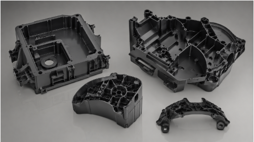
What Makes a Geometry Difficult to Mold?
Not all complex shapes present the same challenges. The geometries that consistently drive up machining time and tooling cost share a few common characteristics: deep, narrow ribs that are difficult to reach with standard cutters, sharp inside corners that require EDM rather than CNC machining, organic contours that require extensive hand polishing, and sections where wall thickness varies dramatically across a single surface.
Deep ribs below a width-to-depth ratio of 1:3 create significant access limitations for milling tools. Cutting these features typically requires small-diameter end mills running at slow feed rates with multiple passes, or EDM operations that add days to the machining schedule. Either way, the cost per feature rises sharply compared to a part with open, accessible geometry.
Impact on Cycle Time and Production Cost
Intricate geometries do not just increase tooling cost during fabrication. They affect cycle time in production as well. Thin walls in isolated areas of an otherwise thick part create uneven cooling, forcing longer cycle times or introducing warping and sink marks that require secondary processing. Every second added to the production cycle multiplies across hundreds of thousands of parts over a tool’s lifetime.
Simplification Strategies During Product Development
The best time to challenge geometric complexity is during early concept review, before industrial design decisions are locked. Replacing organic transitions with compound radii, reducing rib depth, and standardising fillet sizes across a part are changes that take minutes to implement in CAD but can remove hours of machining time from the tooling schedule. Balancing aesthetics with manufacturability is not a compromise; it is a design discipline that produces better products at lower cost.
Case Study: Wearable Electronics Housing A wearable electronics company specified a premium cosmetic finish for all exterior and interior molded surfaces. During the tooling review, engineers identified that the finish requirements would require extensive mold polishing, increase mold fabrication time, and add unnecessary tooling cost. After evaluating the product’s user interaction points, the design team limited premium finishes to visible exterior surfaces, while interior and mating surfaces were assigned functional surface finish grades. This optimization reduced mold finishing effort, shortened tooling lead times, and maintained the desired product aesthetics where they mattered most. |
3. Over-Specifying Cosmetic Surface Finish Requirements
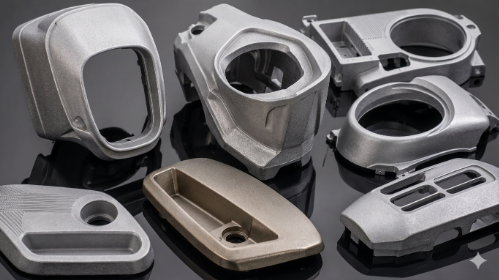
Understanding SPI Surface Finish Standards
The Society of the Plastics Industry defines a graded scale of mold surface finish cost standards, from the rough A-6 through the mirror-polished A-1. Each step up the scale requires progressively more hand polishing time, higher-grade polishing media, and greater skill from the toolmaker. The difference in labour between an SPI B-2 finish and an SPI A-1 finish on a large mold face can represent 40 to 80 hours of additional skilled polishing work.
Why Class-A Surfaces Increase Injection Molding Tooling Cost
Specifying premium cosmetic plastic parts finishes across an entire mold significantly increases both the upfront fabrication cost and the ongoing maintenance burden. Every service interval requires re-polishing to maintain the specified surface quality, and any mold damage, however minor, may require extensive refinishing before production can resume. For products where only a subset of surfaces is actually visible to the end user, blanket premium finish specifications are a straightforward source of avoidable injection molding tooling cost.
The SPI finish standards framework makes it straightforward to assign finish grades on a surface-by-surface basis within the mold specification. Applying a Class-Asurfaces grade only to the visible faces of a housing, while allowing functional surfaces to carry a more practical B or C grade, is standard practice that experienced toolmakers welcome because it simplifies their work and reduces rework risk.
Aligning Design Goals With Budget
Industrial designers and mechanical engineers should review finish specifications together before the mold specification is issued. Identifying which surfaces the user actually sees and touches, and which are hidden by assembly, gaskets, or installation, almost always reveals opportunities to reduce finish requirements without affecting product perception.
Case Study: Wearable Electronics Housing A wearable electronics company specified a premium cosmetic finish for both the exterior and interior surfaces of a plastic enclosure. During the tooling review, engineers identified that achieving a high-gloss finish across all surfaces would require extensive mold polishing, increasing mold fabrication time and tooling cost. After evaluating the product’s user interaction points, the design team limited premium finishes to visible exterior surfaces, while interior and mating surfaces were assigned functional surface finish grades. This approach optimized mold finishing effort while preserving the premium appearance on customer-facing surfaces and avoiding unnecessary manufacturing complexity. |
4. Applying Tight Tolerances Where They Are Not Needed
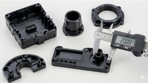
Why Engineers Over-Specify Tolerances
Tight dimensional tolerances are a form of engineering caution. When a designer is unsure which dimensions drive functional performance, the default tendency is to tighten injection molding tolerances across the board to reduce uncertainty. In practice, this transfers the cost of that uncertainty directly to the toolmaker and the quality team, who must build and inspect to specifications that may have no bearing on whether the product works.
Every tolerance tighter than injection molding’s natural process capability requires additional mold manufacturing precision, extended first-article inspection, and ongoing in-process measurement. The cumulative effect on production cost is significant, particularly when tight tolerances are applied indiscriminately to dozens of dimensions on a complex part.
Tolerance Stack-Up Analysis and Optimisation
A formal tolerance stack-up analysis identifies which dimensions are functionally critical and calculates how they interact across an assembly. This analysis makes it possible to specify tight tolerances precisely where the product requires them and to relax tolerances on every other dimension without risk. The result is a tolerance scheme that reflects actual functional requirements rather than blanket caution.
Realistic tolerances for injection-molded parts typically fall in the range of plus or minus 0.1 to 0.3 millimetres for general dimensions, with tighter values achievable for critical features through careful tool design and process control. Specifying tolerances significantly tighter than these ranges without functional justification from geometric tolerancing analysis adds cost without adding performance.
Impact on Quality Control and Production Readiness
Tolerance optimisation also simplifies inspection. Parts with fewer tight-tolerance dimensions require less measurement time per piece, reduce the statistical sampling burden, and lower first-article inspection complexity. The manufacturability gains accumulate across every production batch for the life of the tool.
Case Study: Industrial Monitoring Device An industrial monitoring product was designed with tight tolerances across nearly every molded component. During engineering review, it became clear that only a small number of dimensions were functionally critical for assembly fit and sensor performance. A tolerance stack-up analysis identified areas where specifications could be relaxed without affecting product function. By optimising dimensional requirements, the tooling supplier simplified mold manufacturing and inspection processes, reducing unnecessary machining and quality control effort while maintaining the required assembly accuracy and product performance. |
6. Ignoring Early Toolmaker Feedback
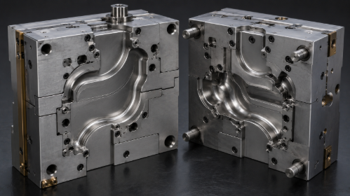
Why Toolmakers Should Be Involved Before Design Is Finalised
Toolmakers see hundreds of molds across a wide range of product categories, and experienced supplier involvement during the design development phase gives engineering teams access to that pattern recognition while changes are still inexpensive. A feature that an industrial designer considers straightforward may be identified by a toolmaker as a maintenance liability or a production risk that adds $10,000 to the mold budget.
Common Manufacturability Issues Identified in Early Reviews
Experienced toolmakers consistently flag a predictable set of issues when reviewing designs: insufficient draft angles on tall features, ribs that are too deep or too narrow to machine cleanly, gate locations that will cause cosmetic witness marks, and ejection layouts that require more lifters than the part geometry warrants. Each of these issues is straightforward to resolve during design but costly to address after tooling has begun.
Injection molding DFM reviews conducted with toolmaker input catch these issues systematically. The combination of design engineering analysis and supplier manufacturability knowledge produces a more complete risk assessment than either discipline can deliver independently.
Concurrent Engineering and Cost Predictability
Companies that involve tooling suppliers early consistently report shorter design-to-production timelines and more accurate tooling budget estimates. When supplier input is incorporated during development, the tooling feasibility review at kickoff becomes a confirmation step rather than a discovery exercise, eliminating the redesign cycles that cause schedule and budget overruns. This is the practical benefit of toolmaker collaboration built into the development process.
Case Study: IoT Gateway Product An IoT company finalized the product design before engaging its tooling supplier. During the mold review, the supplier identified several features that would create molding challenges, increase tooling complexity, and introduce production risk. The resulting redesign delayed tooling release and required additional engineering effort from both the product development and tooling teams. For the next product iteration, the company involved the tooling supplier during the design phase. Potential manufacturability issues were resolved before tooling design began, enabling a smoother transition from product design to mold construction with fewer engineering revisions. |
7. Overengineering Structural Features
Signs of Overengineered Plastic Parts
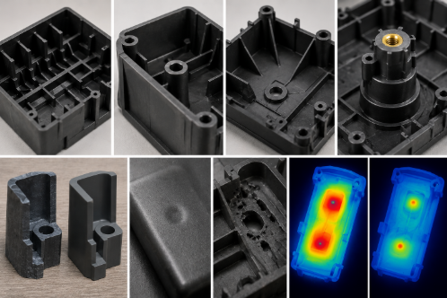
Structural overengineering in plastic parts typically takes the form of excessive rib density, unnecessarily thick walls, redundant gussets, and boss configurations that are far stronger than the application requires. The challenge with injection molding design optimization is that structural performance in plastics depends on geometry and material selection working together. Adding material does not always improve strength, and in some cases thick sections introduce sink marks, voids, and longer cycle times without meaningful performance gain.
Using FEA Before Tooling to Right-Size Structure
Finite element analysis gives engineering teams a data-driven basis for evaluating structural requirements before committing to a design. FEA for plastic parts can identify which ribs and reinforcement features are load-bearing and which are adding weight and complexity without contributing to performance. This makes it possible to achieve plastic part optimization by removing unnecessary material, simplifying mold geometry, and reducing tooling cost without compromising structural integrity.
For hardware startups, avoiding unnecessary structural complexity during the MVP stage can significantly reduce tooling costs and speed up product development. Learn more in our guide on 8 Smart Ways to Build a Cost-Effective Hardware MVP Without Over-Engineering.
Engineering best practices recommend designing plastic parts to meet functional performance with the minimum material and structural complexity necessary, as excessive reinforcement increases tooling complexity, material consumption, molding cycle time, and overall manufacturing cost without delivering proportional performance benefits.
Rib Design Optimisation
Standard rib design optimisation guidelines for injection molding recommend rib thickness at 50 to 60 percent of the adjoining wall thickness to prevent sink marks, base radii of at least 25 percent of rib thickness to reduce stress concentration, and rib height limited to three times the rib thickness to maintain moldability. Following these guidelines produces parts that are structurally efficient and tooling-friendly, with fewer difficult features and more predictable production behaviour. Structural analysis before tooling release makes these decisions data-driven rather than intuitive.
Case Study: Industrial Control Enclosure An industrial equipment manufacturer added extensive ribs and reinforcement features throughout a molded enclosure to improve durability. Simulation studies later revealed that many structural features contributed little to performance under actual loading conditions. Engineers optimised rib placement and wall geometry using finite element analysis (FEA), removing unnecessary material while maintaining the required structural strength.The optimized design delivered the required structural performance with fewer reinforcement features, resulting in a lighter, more moldable component without unnecessary design complexity. |
8. Failing to Standardize Mold Components
Standard vs Custom Mold Components
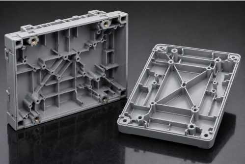
Injection molds are built around a combination of custom-machined cavities and cores, and commercially available standard mold components including mold bases, ejector pins, guide bushings, hot runner systems, and support pillars. Standard components are stocked by multiple suppliers, priced competitively, and available quickly. Custom components must be designed, quoted, sourced, and machined individually, which adds cost, lead time, and long-term maintenance complexity.
Cost Savings and Lead Time Benefits of Standardisation
Designing tools around mold base standardisation principles reduces initial tooling cost, shortens build lead times, and simplifies the maintenance supply chain. When standard components need replacement during production, they can typically be sourced and installed within days. Custom components may require weeks to procure or fabricate, creating extended production downtime that is far more expensive than the component itself.
Industry toolmakers estimate that standardising mold components across a product family can reduce mold tooling cost reduction by 10 to 20 per cent per tool and shorten tooling lead time by two to four weeks, depending on the level of customisation eliminated. For companies managing multiple simultaneous tooling programs, the compounding benefit of standardisation across the portfolio is substantial.
Industry experience consistently shows that identifying opportunities for mold component standardisation during the design stage helps reduce redesign cycles, shorten tooling lead times, simplify maintenance, and minimize costly engineering changes later in the program.
Long-Term Serviceability and Procurement Advantages
Standard components also make it possible to service a tool with a different toolmaker if the original supplier is unavailable or if the tool is relocated to a different production facility. This flexibility has significant value in supply chain disruption scenarios and gives manufacturers more leverage in long-term tooling maintenance negotiations.
Case Study: Mobile Accessory Product A mobile accessory manufacturer initially designed a mold that required several custom components and a non-standard mold base configuration. During the tooling review, suppliers identified that sourcing custom components would increase costs, extend lead times, and create future maintenance challenges. They recommended redesigning the tool around a standard mold base and readily available components.The revised design standardized critical mold components, improving spare-part availability, simplifying future maintenance, and providing greater flexibility to support production across different tooling suppliers without affecting product functionality or quality. |