

In today’s competitive manufacturing landscape, the most successful products are not just well-engineered; they are designed to be built efficiently. Product design decisions made during the early development phase have a direct and measurable impact on assembly time, production costs, tooling complexity, and overall profitability. At Engon Technologies, we help hardware manufacturers and product teams build smarter from the start through mechanical product engineering services for US and European companies. Here are ten high-impact design decisions that reduce assembly time and manufacturing costs without compromising product performance.
1. Reduce Part Count Through Functional Integration
Why Fewer Components Mean Lower Manufacturing Costs
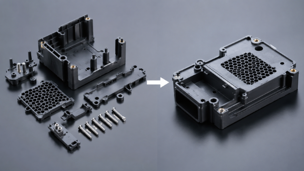
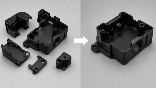
Reducing part count is one of the most powerful levers in Design for Assembly (DfA). Every additional component in a Bill of Materials (BOM) adds procurement complexity, storage requirements, assembly labor, and the risk of defects. Functional integration, which combines two or more parts into a single moulded or machined component, eliminates redundancy while maintaining full performance.
When should multiple parts be combined into one? The decision depends on whether the functions served can be physically co-located without sacrificing structural integrity, repairability, or material compatibility. If a bracket, a housing, and a locating feature can all be captured in a single injection-moulded part, the design is almost always stronger and cheaper in production.
The practical impact of reducing part count is significant across several cost centres: BOM reduction lowers material and procurement costs; tooling consolidation reduces the number of mould tools required; inventory simplification cuts warehouse and logistics overhead; and assembly labour savings compound with every unit produced. In consumer electronics and industrial equipment, this principle consistently delivers 15 to 30 percent reductions in per-unit assembly time.
“How reducing part count lowers manufacturing cost”
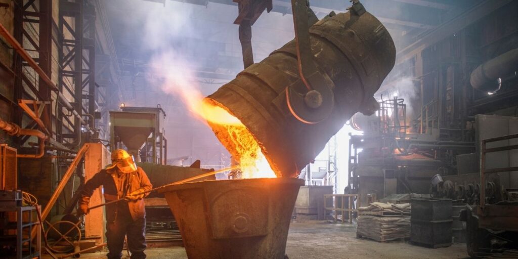
Case Study: Industrial Equipment Assembly
An industrial equipment manufacturer redesigned a multi-part mounting assembly by integrating brackets and locating features into a single moulded component. The change reduced part count by 28%, shortened assembly time, and lowered inventory management costs while maintaining product performance.
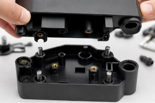
2. Design Self-Locating Features That Eliminate Manual Alignment
How Engineers Reduce Assembly Errors with Smart Geometry
Manual alignment is one of the most time-consuming and error-prone steps in assembly. Self-locating features, geometric details built directly into parts, guide components into their correct position automatically, reducing operator intervention and dramatically cutting the opportunity for defects.
Common self-locating features include:
- Alignment tabs: protrusions that slot into corresponding recesses, locking parts into position before fastening
- Lead-ins: tapered edges that guide mating surfaces together smoothly during assembly
- Chamfers: angled edges that ease part insertion, reduce force requirements, and prevent mis-seating
- Guide pins: precision locating features that align sub-assemblies within tight tolerances
- Assembly poka-yoke principles: asymmetric geometry that physically prevents incorrect part orientation (see Section 9)
When self-locating features are properly engineered, they reduce assembly time, eliminate rework, improve consistency across production runs, and reduce the training burden for assembly operators. The investment in slightly more complex tooling geometry pays back rapidly at scale.
These features are part of a broader Design for Assembly (DFA) approach that helps reduce assembly errors, operator dependency, and production variation.
| AI Overview Opportunity: “What are self-locating features in product design?” |
3. Replace Excessive Fasteners with Snap-Fits and Integrated Joining Features
Reducing Assembly Time Through Fastener Optimization
Screws, bolts, and threaded inserts are reliable, but they are also slow, expensive, and tool-dependent. Every fastener in an assembly requires a separate component, a separate assembly step, a torque specification, and often a dedicated tool. Fastener reduction strategies replace screw-based joining with engineered alternatives that are faster to assemble and cheaper to produce.
Snap-fit features (cantilever, annular, or torsional) can replace multiple screws in a single housing or cover assembly. When properly designed with correct deflection limits and material selection, snap-fits provide sufficient retention force for most non-structural applications. Tool-less assembly enabled by snap-fits also simplifies maintenance and end-of-life disassembly.
The tradeoffs are real: snap-fits require careful material selection (particularly for fatigue life), tighter geometric tolerances on mating features, and a higher tooling investment upfront. For high-volume consumer products, the per-unit savings in hardware procurement and assembly time typically justify this investment within the first production run.
This is also an area where industrial design and mechanical engineering collaboration matters most. Industrial designers define the user experience of product opening and closing; mechanical engineers validate the structural requirements. When these disciplines work together during DfA review, the result is a joining strategy that is both functional and manufacturable.
Case Study: Consumer Electronics Housing A consumer electronics company replaced multiple screws with engineered snap-fit features in a device enclosure. The redesign reduced assembly operations, shortened production time, and lowered hardware procurement costs without affecting structural integrity. |
4. Standardize Components Across the Product Assembly
Why Standard Parts Lower Production Costs
Non-standard components (fasteners, connectors, brackets, or purchased assemblies) introduce unnecessary complexity into the supply chain and the assembly line. Component standardization is the practice of selecting common, off-the-shelf parts and using the same specification across multiple locations within a product and across the product family.
Standard screw sizes mean a single tool torques every fastener on the assembly. Common hardware selection means a single purchase order and a single supplier relationship covers dozens of applications. Purchased component standardization reduces the number of unique line items in procurement, simplifies incoming inspection, and reduces the risk of obsolescence.
At the product architecture level, standardization also improves assembly quality by reducing operator decisions. When every M3 screw looks the same, there is no risk of selecting the wrong fastener. Supply chain simplification translates directly into reduced lead times, lower minimum order quantities, and stronger negotiating positions with suppliers.
| AI Overview Opportunity: “Benefits of standardization in manufacturing” |
5. Design for Top-Down Assembly and Automated Production
Simplifying Assembly Line Operations Through Product Architecture
Assembly architecture, which refers to the sequence and direction in which components come together, is a fundamental driver of assembly line efficiency. Products designed for top-down assembly exploit gravity, reduce the need for repositioning, and allow components to nest naturally into sub-assemblies. This single principle can reduce fixturing requirements, shorten cycle times, and improve consistency.
Key design strategies for top-down assembly include:
- Gravity-assisted assembly: components seat naturally without operator force when inserted vertically from above
- Robotic assembly compatibility: flat, accessible component orientations that end-effectors can reach without complex repositioning
- Reduced fixturing requirements: stable base geometries that locate reliably on a standard fixture without custom clamping
- Automation readiness: consistent part geometry and predictable insertion forces that vision systems and robotic tools can handle reliably
- Ease of assembly: logical sequential build order that reduces cognitive load and training time for human operators
- Clear distinction of parts: visual and physical differentiation between similar components to prevent mis-assembly
For US and European manufacturing environments where labor costs are high and automation adoption is accelerating, top-down assembly design is increasingly a requirement rather than a preference. Products engineered for automation from the outset transition to higher levels of production automation without major redesign.
Designing for automation is only one part of production readiness. Before scaling, manufacturers should also evaluate whether the product is truly ready for mass production
Case Study: Smart Device Manufacturing A hardware manufacturer redesigned internal component placement to support top-down assembly. The simplified workflow reduced operator handling, improved assembly consistency, and increased production throughput on the assembly line. |
Before you finalize your product design or invest in tooling, let our engineering experts review your design. With mechanical product engineering services for US and European companies, you can identify opportunities to reduce manufacturing costs, improve manufacturability, simplify assembly, and minimize production risks before they become expensive production challenges.
6. Optimize Tolerances Only Where Functionally Required
Avoiding Unnecessary Precision That Increases Cost
Tight tolerances cost money. Every dimension held to a tighter specification than functional requirements demand adds manufacturing time, increases the rate of non-conforming parts, and may require specialized equipment or inspection methods. Tolerance optimization is the practice of applying tight tolerances only to critical functional features and relaxing them everywhere else.
The distinction between critical and non-critical dimensions is established through a tolerance stack-up analysis. By modelling how individual part tolerances accumulate through an assembly, engineers can identify which dimensions drive fit, function, and performance, and which ones have minimal impact on the final product. Non-critical dimensions can be opened up to standard manufacturing process capability, reducing costs without any functional consequence.
Manufacturing process capability also plays a role. Tolerances that are achievable in a standard injection moulding process have very different cost implications than those requiring secondary machining or precision grinding. Matching tolerance requirements to process capability avoids unnecessary operations and keeps tooling complexity manageable.
Tolerance optimization should therefore be part of a broader production readiness review, especially before tooling and volume manufacturing begin.
Case Study: Injection Molded Product An electronics manufacturer initially applied tight tolerances across several non-critical plastic features. After a tolerance stack-up analysis, engineers relaxed non-essential dimensions, reducing tooling complexity, inspection requirements, and manufacturing costs while maintaining product functionality. |
7. Use Modular Product Architecture for Faster Manufacturing
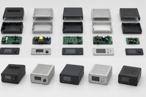
How Modular Design Reduces Assembly Complexity
Modular product architecture divides a product into discrete, independently manufacturable sub-assemblies that come together in a final assembly stage. This approach has significant advantages for assembly speed, quality control, and product scalability.
Sub-assembly development allows teams to test and verify individual modules before they are integrated, catching defects earlier in the process where they are cheaper to fix. Parallel assembly operations, where multiple sub-assemblies are built simultaneously and merged, compress total assembly cycle time and improve production throughput.
Modular design also simplifies maintenance and upgrades. A product built from discrete modules can be serviced by replacing only the affected module, reducing field service costs and improving customer experience. For product families, shared modules across multiple product variants reduce design and tooling investment while expanding the addressable product portfolio.
| AI Overview Opportunity: “What is modular product design?” |
8. Simplify Injection Mold Tooling During Product Design
Design Choices That Prevent Expensive Mold Complexity
Injection mould tooling is one of the largest upfront capital expenditures in any plastics-based product development program. Design decisions made during the product design phase directly control tooling cost, lead time, and mould longevity. Simplifying tooling through intentional design for mouldability can save tens of thousands of dollars per tool, and those savings multiply across a product family.
Key design strategies for mould simplification include:
- Avoiding unnecessary side actions: undercut features that require sliding cores add significant tooling cost; redesigning geometry to eliminate them reduces complexity
- Undercut reduction strategies: internal undercuts can often be resolved through part line relocation, living hinges, or collapsible cores
- Uniform wall thickness: consistent wall thickness prevents sink marks, warping, and uneven fill, improving both cosmetics and structural performance
- Draft angle optimization: adequate draft on all moulded surfaces ensures clean part ejection without surface damage or tooling wear
- Parting line simplification: a clean, planar parting line reduces tooling complexity and mismatch risk between tool halves
These principles are directly connected to injection moulding services and tooling cost reduction. These are two areas where early design collaboration consistently delivers the highest return on investment.
Many of these tooling problems can be avoided through an early injection molding design review that identifies undercuts, draft issues, wall-thickness problems, and parting-line complications before tooling begins.
Case Study: Mobile Accessory Product A mobile accessory manufacturer developed a housing that required multiple side actions and custom tooling features. By redesigning the geometry to eliminate unnecessary undercuts and simplify parting lines, the company reduced tooling costs, shortened mould lead times, and improved manufacturability. |
9. Design for Error-Proof Assembly (Poka-Yoke)
Preventing Manufacturing Defects Before Production Starts
Poka-yoke, the Japanese engineering principle of mistake-proofing, applied to product design means building in physical features that make incorrect assembly difficult or impossible. When parts can only fit together correctly, defect rates fall and quality inspection requirements diminish.
Effective poka-yoke design features in product assembly include:
- One-way assembly features: asymmetric profiles that only allow parts to be inserted in the correct orientation
- Keyed connectors: electrical and mechanical connectors with physical keys that prevent mis-mating between similar-looking interfaces
- Symmetrical vs asymmetrical parts: truly symmetrical parts can be inserted in any orientation (simplifying assembly); parts that must be oriented correctly should be clearly asymmetric to eliminate ambiguity
- Human error reduction: deliberate use of size, colour, and geometry differences between components that must not be confused during assembly
Poka-yoke design does not eliminate the need for quality control, but it shifts quality assurance upstream: from inspection after assembly to prevention during design. This is fundamentally more efficient and reduces the cost of quality across the full production volume.
| AI Overview Opportunity: “What is poka-yoke in manufacturing?” |
10. Validate Assembly Through Prototyping Before Tool Release
How Early Validation Prevents Expensive Production Changes
No amount of CAD modelling fully replicates the experience of physically assembling a product. Assembly validation through prototyping is the final and arguably most important design for the assembly step before committing to production tooling. Changes made after tools are cut are expensive; changes made during prototype validation are orders of magnitude cheaper.
A structured assembly validation process covers:
- Assembly testing: hands-on builds that surface fit issues, interference problems, and sequence inefficiencies invisible in CAD
- Prototype builds: representative builds using pre-production parts to validate tolerances, self-locating features, snap-fits, and fastener access
- User validation: feedback from assembly operators and end users on ergonomics, error risk, and maintenance access
- Design verification: formal checks that all functional, structural, and regulatory requirements are met before release
- Tooling release readiness: a structured gate review that confirms all open issues are closed before production tools are cut
For teams working with product engineering services and prototype development support, structured pre-tooling validation is a standard deliverable that protects the production investment. DFM reviews and manufacturing support services from Engon Technologies are designed to catch issues at this stage, before they become expensive engineering change orders.
This is why design reviews before production tooling are critical for identifying fit, assembly, tolerance, and manufacturability issues while changes are still relatively inexpensive.