
10 Design Mistakes That Increase Injection Mold Tooling Costs and How to Avoid Them
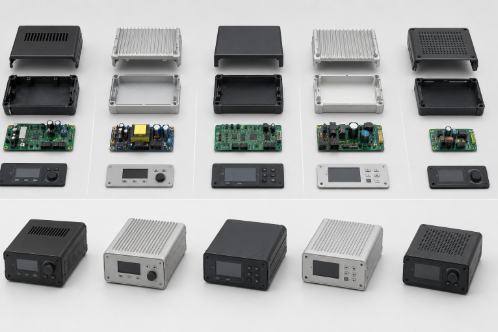
Tooling is one of the largest upfront investments in any injection-molded product. For most projects, the mould itself represents 30 to 60 percent of total product development cost, and those numbers can climb fast when the design is not built with manufacturability in mind. The frustrating reality is that most tooling cost overruns are not caused by poor supplier selection or unexpected material prices. They are locked in during the design phase, often weeks or months before a purchase order is issued, highlighting the importance of engineering services for product development for engineering managers across the US and Europe to improve manufacturability before tooling begins. Industry research indicates that approximately 70–80% of a product’s total lifecycle cost is determined during the early design phase, making design decisions one of the biggest drivers of tooling cost, manufacturability, and long-term production efficiency. This guide walks through ten design decisions that consistently drive up injection mold tooling costs, along with practical strategies engineers and product teams can use to avoid them. Each section includes a real-world case study to show how the principles apply in practice. Before investing in production tooling, it’s equally important to evaluate whether your product is truly ready for manufacturing. Our guide on Is Your Product Really Ready for Mass Production? explains the key engineering and manufacturability checks that help reduce production risks before tooling begins. 1. Designing Features That Require Side Actions, Sliders, and Lifters What Are Side Actions, Sliders, and Lifters? Side actions in injection molding are mechanical mechanisms built into a mold to form features that cannot be released by opening the mold along its primary axis. Sliders move horizontally to create external undercuts such as lateral holes or recesses, while lifters in injection molds move at an angle to release internal undercut features during part ejection. Both add significant mechanical complexity to the tool. How Undercuts Drive Up Mold Complexity and Cost Every undercut design feature in a design requires a corresponding mechanism in the mold. Each mechanism adds machined components, wear surfaces, cooling considerations, and assembly points. A simple two-plate mold with no side actions can be designed, machined, and assembled in a fraction of the time a mold with four or five mechanisms requires. Beyond initial build cost, mechanisms increase long-term maintenance frequency and the likelihood of production downtime. The cost impact of mold complexity caused by side actions is significant. Industry estimates suggest each additional side action can add 8 to 15 percent to total tooling cost depending on the mechanism size and accessibility within the tool. For a baseline mold in the $40,000 to $80,000 range, three or four side actions can translate to an additional $15,000 to $30,000 in tooling investment before production begins. Design Alternatives and DFM Strategies The most effective way to control mold construction cost is to eliminate undercuts during the design phase through geometry modification. Repositioning holes to align with the draw direction, splitting features across two mold halves, or adding draft to recessed areas can often remove the need for mechanisms entirely. When side actions are unavoidable because functional requirements demand the feature, toolmakers should be consulted early to select the lowest-complexity mechanism that satisfies the design intent. DFM reviews that focus specifically on injection mold tooling costs will flag every potential side action before mold design begins, giving engineering teams the option to simplify while design changes are still inexpensive. According to product development and systems engineering studies, engineering changes made after tooling begins can cost 10 to 100 times more than changes implemented during the design stage, reinforcing the value of identifying side actions and undercuts as early as possible.Following a structured design review process is equally important for identifying manufacturability risks before design freeze—learn more in our guide on Design Review Mistakes That Lead to Costly Production Delays. Case Study: Smart Home Controller EnclosureA smart home device manufacturer developed a plastic enclosure with multiple side openings for cable routing and mounting features. The initial design required four side actions and two lifters, increasing mold complexity, machining effort, and tooling cost. During a Design for Manufacturability (DFM) review, engineers modified the enclosure geometry to eliminate unnecessary undercuts and reposition critical features in line with the mold opening direction. The revised design reduced the number of side actions, simplified mold construction, shortened tooling lead times, and lowered overall tooling investment while maintaining the product’s functional requirements. As a result, the project progressed to production with lower manufacturing risk and fewer tooling-related delays. 2. Creating Intricate Geometries That Increase Mold Complexity What Makes a Geometry Difficult to Mold? Not all complex shapes present the same challenges. The geometries that consistently drive up machining time and tooling cost share a few common characteristics: deep, narrow ribs that are difficult to reach with standard cutters, sharp inside corners that require EDM rather than CNC machining, organic contours that require extensive hand polishing, and sections where wall thickness varies dramatically across a single surface. Deep ribs below a width-to-depth ratio of 1:3 create significant access limitations for milling tools. Cutting these features typically requires small-diameter end mills running at slow feed rates with multiple passes, or EDM operations that add days to the machining schedule. Either way, the cost per feature rises sharply compared to a part with open, accessible geometry. Impact on Cycle Time and Production Cost Intricate geometries do not just increase tooling cost during fabrication. They affect cycle time in production as well. Thin walls in isolated areas of an otherwise thick part create uneven cooling, forcing longer cycle times or introducing warping and sink marks that require secondary processing. Every second added to the production cycle multiplies across hundreds of thousands of parts over a tool’s lifetime. Simplification Strategies During Product Development The best time to challenge geometric complexity is during early concept review, before industrial design decisions are locked. Replacing organic transitions with compound radii, reducing rib depth, and standardising fillet sizes across a part are changes that take minutes to implement
10 Design Mistakes That Increase Injection Mold Tooling Costs and How to Avoid Them Read More »