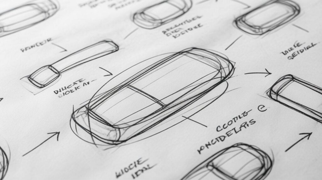
7 DFM Engineering Techniques to Reduce IoT Enclosure Manufacturing Costs Before Production
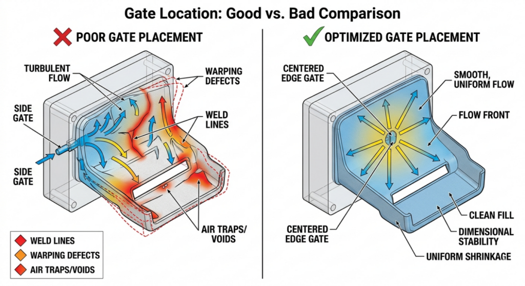
Most hardware startups realize the importance of DFM for injection molding only at advanced stages of tooling. At that stage, even minor modifications require expensive tool rework, causing delays and significant cost overruns. DFM is not a checklist to run through at the end of your design process. It is a discipline that must shape every decision from the earliest concept stages. Applied correctly, it reduces manufacturing costs, improves yield, shortens cycle times, and makes your product far easier to scale when the time comes. This is why many global teams now rely on mechanical product engineering for startups in the US and Europe to ensure DFM is embedded right from the concept stage. This article covers 7 proven techniques for injection molding cost reduction, that directly impact manufacturing costs for IoT enclosures with real case studies that show exactly what poor decisions look like in practice, and what thoughtful design can save. 1. DFM for Injection Molding: Costly Gate Design Mistakes How to optimize gate location in injection molding to avoid costly defects In injection moulding, the gate is the entry point through which molten plastic flows into the mould cavity. A well-planned injection molding gate design determines almost everything about how your part fills, where weld lines form, and whether the finished part warps or remains dimensionally stable. There are several gate types to consider: edge gates are simple and low-cost but can leave visible marks; pin gates offer cleaner aesthetics but require more complex tooling; hot runner systems eliminate gate vestiges entirely but carry significantly higher upfront tooling costs. The right choice depends on your part geometry, production volume, and cosmetic requirements, especially when targeting injection molding cost reduction without compromising quality. Flow balance is the critical concept. When plastic enters from an optimally positioned gate, it fills the cavity evenly, pushing air out through vents uniformly, and cooling with consistent shrinkage across the part. Poor gate placement creates race tracking where plastic flows faster through thicker sections and meets itself at weld lines. These weld lines are structural weak points and often cosmetically visible. Using mold flow analysis, engineers can simulate and validate gate positions before committing to tooling. This is not an expensive luxury; it is one of the most cost-effective investments in the entire product development process. Case Study: Consumer Electronics Startup, United States Problem: Incorrect gate placement caused uneven material flow, leading to high rejection rates and visible warping in the finished enclosures. Impact: Significant scrap costs are accumulating with every production run. Assembly delays and quality control failures. Fix: Flow simulation used to identify optimal gate repositioning. Tooling was modified before high-volume production commenced. Result: Defect rate was eliminated. Approximately $20,000 saved in scrap and rework costs. Key Insight: Flow balance directly determines your cost per accepted part. 02.Parting Line Design Mistakes That Drive Up Tooling Cost How parting line design affects tooling cost in plastic parts The parting line is where the two halves of your injection mould meet. Effective parting line design in injection molding is one of the most consequential design decisions in plastic part development and one that is frequently underestimated by startups unfamiliar with tooling economics. In DFM for injection molding, parting line strategy plays a critical role in controlling tooling complexity and overall cost.Every time your part geometry forces the mould to split in a complex direction, or requires side actions and lifters to release undercuts, your mold design complexity cost increases These mechanisms drive up cost, add machining time, increase mould maintenance requirements, and introduce additional failure points in production. Simpler parting geometry equals cheaper, more reliable tooling and contributes directly to injection molding cost reduction. Flash defects in of plastic that form at the parting line are another consequence of poor strategy. When mould halves do not align perfectly, or when injection pressure forces plastic into tiny gaps, flash forms and must be removed manually or through secondary operations. At volume, this adds meaningful labor cost. The best approach is to define your parting line during the earliest stages of enclosure design, not as a downstream manufacturing consideration. Place parting lines on non-cosmetic edges where possible. Design draft angles that allow clean release. Eliminate undercuts through geometry changes rather than mechanical mould features wherever feasible. Case Study: Industrial IoT Startup, Germany Problem: Complex parting geometry required multiple side-actions and non-standard mould split directions to accommodate the enclosure design Impact: Tooling cost increased by €35,000 over initial estimates. Extended lead time for mould manufacture. Fix: Design team simplified the split line geometry, eliminating two side actions through minor enclosure shape changes Result: Tool cost reduced by 20%. Manufacturing setup time shortened. Ongoing maintenance costs have been lowered. Key Insight: Simpler geometry is always cheaper to tool and easier to maintain 3. DFM for Injection Molding: Snap-Fit vs Screws to Reduce Assembly Cost How to reduce assembly cost in hardware products using snap-fits Every fastener in your assembly has a cost. Not just the cost of the screw itself, though that adds up at volume, but the cost of the driver tool, the assembly time per unit, the torque specification and quality check, the potential for cross-threading or over-torquing, and the service time when a field technician needs to open the device. This is why the decision between snap fit design vs screws has a direct impact on overall manufacturing efficiency and cost. Snap-fit joints, when designed correctly, eliminate most of these costs. A well-designed cantilever snap-fit can be engaged in a fraction of a second with no tools, no fasteners, and no torque variability. At a production volume of one million units, reducing assembly time by thirty seconds per unit translates directly into thousands of dollars in labor savings making it a key strategy in IoT enclosure design for manufacturing. The trade-off is engineering complexity and material discipline. Snap-fits require careful geometry to achieve the right deflection force without fracturing the feature. They require consistent material properties, particularly